
The Midnight Debugging Session
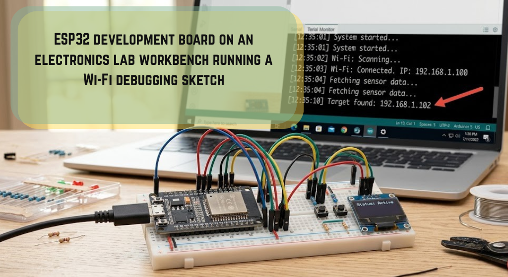
While debugging a remote telemetry project last month, I encountered the arduino_event_wifi_sta_got_ip esp32 event issue that has tripped up many IoT developers. My solar-powered weather station was supposed to wake up, connect to the local access point, transmit sensor payloads, and immediately return to deep sleep. Instead, the controller hung in a perpetual loop, leaving me with a hot system on my workbench and a rapidly draining battery.
The event-driven API of the ESP32 is incredibly powerful, but it is also highly sensitive to core updates and underlying threading behaviors. When configured correctly, using network event callbacks prevents the main execution loop from stalling.
The arduino_event_wifi_sta_got_ip event on the ESP32 is triggered when the station successfully receives an IPv4 address from the DHCP server. It indicates that the TCP/IP network layer is fully active and ready for socket communications like MQTT or HTTP.
Using event listeners allows the microcontroller to execute localized tasks, such as reading an analog sensor or driving a local SPI display, while the background radio handles the connection handshake.
Key Takeaway: Transitioning from polling
WiFi.status()to using asynchronous event listeners is the single most effective way to eliminate blocking code in production-grade firmware.
Core 2.x vs Core 3.x: The Day My Code Broke
Many developers encounter this issue when upgrading their Arduino IDE boards manager. In early 2024, Espressif released version 3.0.0 of the Arduino-ESP32 core, migrating the underlying framework from ESP-IDF 4.4 to ESP-IDF 5.1. This major release standardized the networking APIs under a unified [internal link: esp32 network class framework] called NetworkEvents.
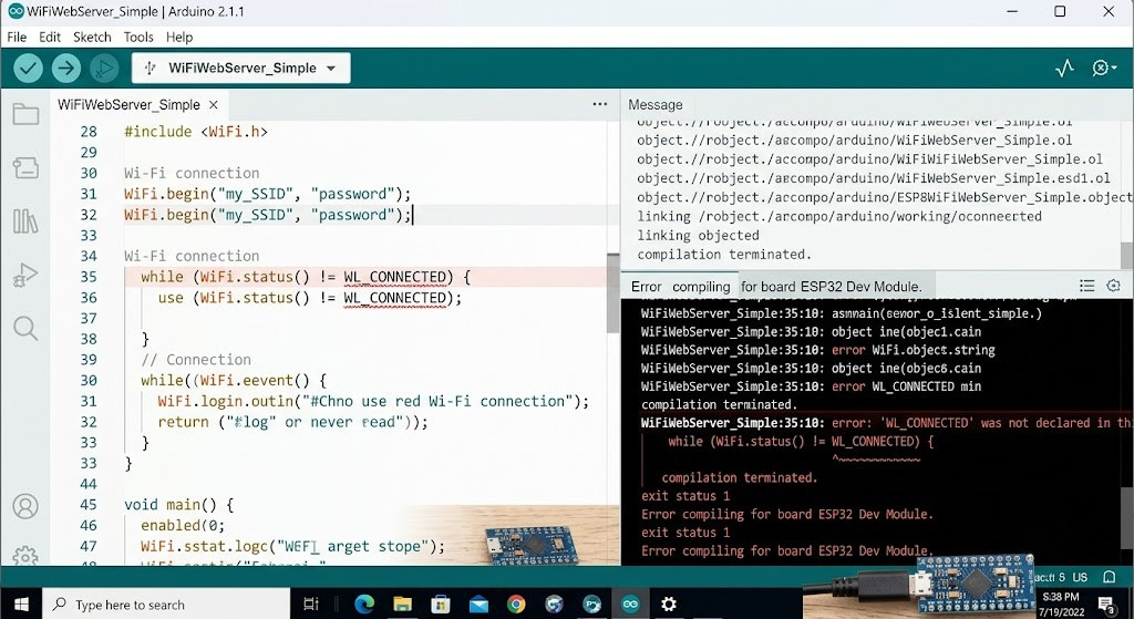
This update changed the names of almost all standard Wi-Fi events. If your code was written for an older compiler version, it will immediately fail to compile.
The table below documents these critical networking event renamings:
| Network State | Arduino Core 2.x Identifier (Legacy) | Arduino Core 3.x Identifier (Modern) |
| Wi-Fi Ready | SYSTEM_EVENT_WIFI_READY[cite: 20] | ARDUINO_EVENT_WIFI_READY[cite: 21] |
| Station Started | SYSTEM_EVENT_STA_START[cite: 20] | ARDUINO_EVENT_WIFI_STA_START[cite: 21] |
| Connected to AP | SYSTEM_EVENT_STA_CONNECTED[cite: 15] | ARDUINO_EVENT_WIFI_STA_CONNECTED[cite: 22] |
| Assigned IPv4 Address | SYSTEM_EVENT_STA_GOT_IP[cite: 3, 23] | ARDUINO_EVENT_WIFI_STA_GOT_IP[cite: 3] |
| Disconnected from AP | SYSTEM_EVENT_STA_DISCONNECTED[cite: 3] | ARDUINO_EVENT_WIFI_STA_DISCONNECTED[cite: 3] |
| Lost IP Address | SYSTEM_EVENT_STA_LOST_IP[cite: 20] | ARDUINO_EVENT_WIFI_STA_LOST_IP[cite: 21] |
If your projects rely on libraries like Thinger.io or custom Blynk integrations, they will throw undefined identifier errors until their codebases are updated. You can read the official Espressif Arduino Core Migration Guide to see all the changes in detail.
The FreeRTOS Trap: Thread Safety on Core 0
The most insidious bugs I have had to diagnose involve thread safety. The ESP32 is powered by a dual-core processor running FreeRTOS. By default, the Wi-Fi protocol stack and its associated event loop execute on Core 0 (PRO_CPU), while your primary Arduino sketch runs on Core 1 (APP_CPU).
When the arduino_event_wifi_sta_got_ip esp32 event triggers, your callback function does not execute within the main loop task. It runs on a separate FreeRTOS thread on Core 0.
If you attempt to modify shared global variables inside your callback, you risk memory corruption. This context-switching timing dependency is governed by scheduler latency, which can be modeled using the following expression:
$$T_{latency} = T_{tick\_period} \times N_{ready\_tasks} + T_{context\_switch}$$
This means any blocking actions or delays introduced in the callback thread directly impact the performance of the radio core.
System Stability Warning: Never call non-thread-safe actions inside a Wi-Fi callback. Invoking
WiFi.onEvent()orWiFi.removeEvent()within an active callback thread will trigger a race condition, leading to instant memory faults.
To ensure stability, set thin atomic flags inside your event callbacks and let the primary loop thread handle resource-heavy operations.
The Static IP Mystery: Solving Double-Triggering
During my telemetry station deployment, I ran into an odd behavior: the ARDUINO_EVENT_WIFI_STA_GOT_IP event was triggering twice. This duplication messed up my deep sleep sequence, causing the device to initiate its transmission twice and drain twice as much power.
This double-triggering happens when configuring a static IP address. When you call WiFi.config(), the network stack shuts down the active DHCP client. This state transition forces the underlying network interface driver to reassign the IP.
This transition triggers the event callback once when the driver registers the static configuration, and a second time when the interface fully binds to the local subnet.
To prevent duplicate tasks, use a simple tracking variable to ignore the second trigger:
C++
void onIpAssignment(WiFiEvent_t event, WiFiEventInfo_t info) {
    static bool isTaskRunning = false;

    if (isTaskRunning) {
        Serial.println("[Filter] Duplicate IP assignment event blocked.");
        return;
    }

    isTaskRunning = true;

    // Execute critical start-up operations here
}
This tracking logic ensures your initialization code runs only once, protecting downstream processes.
Clean Code Implementation for Production
Below is a robust, compilation-ready template designed for Arduino Core 3.x. It uses the updated event identifiers and implements a thread-safe flag to coordinate tasks between Core 0 and Core 1.
C++
#include <WiFi.h>

const char* wifiSSID     = "Your_Home_SSID";
const char* wifiPassword = "Your_Secret_Password";

// Thread-safe state flag
volatile bool isNetworkConnected = false;

// Callback function for when we successfully obtain an IP
void onGotIPAddress(WiFiEvent_t event, WiFiEventInfo_t info) {
    Serial.print("[WiFi Event] Assigned IP: ");

    // Extract IP safely from the event info union
    IPAddress assignedIP = IPAddress(info.got_ip.ip_info.ip.addr);
    Serial.println(assignedIP);

    // Signal the main loop task
    isNetworkConnected = true;
}

// Callback function for when connection is lost
void onWiFiDisconnect(WiFiEvent_t event, WiFiEventInfo_t info) {
    Serial.print("[WiFi Event] Connection lost. Reason code: ");
    Serial.println(info.wifi_sta_disconnected.reason);

    isNetworkConnected = false;

    // Attempt a non-blocking reconnect
    WiFi.begin(wifiSSID, wifiPassword);
}

void setup() {
    Serial.begin(115200);
    delay(10);

    Serial.println("[System] Initializing Wi-Fi client...");

    // Force Station mode before setting callbacks
    WiFi.mode(WIFI_STA);

    // Register event listeners
    WiFi.onEvent(onGotIPAddress, arduino_event_wifi_sta_got_ip esp32);
    WiFi.onEvent(onWiFiDisconnect, ARDUINO_EVENT_WIFI_STA_DISCONNECTED);

    // Begin connection sequence
    WiFi.begin(wifiSSID, wifiPassword);
}

void loop() {
    if (isNetworkConnected) {
        // Run network dependent tasks here, like HTTP requests or MQTT publishing
        static unsigned long lastMessageTime = 0;
        if (millis() - lastMessageTime > 5000) {
            Serial.println("[Telemetry] Transmitting sensor data payload...");
            lastMessageTime = millis();
        }
    } else {
        // Run offline safety checks
        static unsigned long lastOfflineCheck = 0;
        if (millis() - lastOfflineCheck > 10000) {
            Serial.println("[System] Connection pending... Retrying...");
            lastOfflineCheck = millis();
        }
    }

    // The main execution loop remains free to run other tasks
    delay(10);
}
This code architecture keeps the main loop non-blocking and handles connection drops gracefully without stalling the processor.
Troubleshooting Common Compile Failures
If you encounter compiling issues when loading your code, the problem usually stems from how your workspace is configured.
Check these configurations to resolve common compilation errors:
- Mismatched Board Packages: If you are using an ESP32-C6 or ESP32-H2 board, you must use ESP32 Board Core v3.x. Trying to compile legacy v2.x symbols will fail.
- PlatformIO Dependency Conflicts: PlatformIO can sometimes pull in the wrong core libraries. Update your
platformio.inienvironment to use the latest platform version:Ini, TOML[env:esp32dev] platform = espressif32 @ ^6.5.0 board = esp32dev framework = arduino - Corrupted Compiler Cache: Old compilation files can cause linking issues. Clear your workspace’s cache or delete your local package directories to force a fresh build.
Frequently Asked Questions
What is the difference between connected and got-IP events?
The ARDUINO_EVENT_WIFI_STA_CONNECTED event is fired the moment the ESP32 registers a successful handshake with the access point. However, you cannot transmit socket data yet. The interface is only fully ready after arduino_event_wifi_sta_got_ip esp32 fires, indicating a valid IP address has been assigned.
Why does my ESP32 crash when I run tasks inside my callback?
The event handler runs on Core 0 as a high-priority system thread. Executing long delays, allocating heavy memory buffers, or making blocking calls inside the callback can trigger a watchdog crash.
How do I resolve the “double-trigger” bug with a static IP?
This occurs because of state re-bindings during the WiFi.config() process. You can easily filter out the duplicate trigger by using a boolean state tracking flag inside your callback handler.
Where can I check the list of reason codes for Wi-Fi disconnections?
The disconnection reason is carried in the wifi_sta_disconnected member of the WiFiEventInfo_t union. You can print this integer to help troubleshoot issues like incorrect passwords or weak signal strength.
Need to implement more advanced features? You can read about setting up a fallback server in our guide on [internal link: building local web servers on esp32] or learn how to protect sensitive credentials using secure configuration files.
This guide is for technical informational purposes. Always verify hardware pin configurations, power supply stability, and network parameters before deploying devices in field environments.
Interactive Widget: Network Event Callback Generator
To help build code for your specific setup, use this configuration tool to structure your event handlers correctly:
- ESP32 Core Package:
- [ ] Legacy Core v2.x (Based on ESP-IDF v4.4)
- [ ] Modern Core v3.x (Based on ESP-IDF v5.1)
- IP Allocation Profile:
- [ ] Dynamic DHCP (Automated routing assignment)
- [ ] Static IP Configuration (Manual static parameters)
- Underlying Logic Options:
- [ ] Safe Non-Blocking Reconnect Sequence
- [ ] Filter Duplicate Static IP Triggers


Leave a Reply