Why I Almost Sent My First Core ESP32-C3 Board Back
My first core ESP32-C3 board for Arduino sat in a static bag on my desk for almost two weeks before I worked up the nerve to plug it in. It came from a marketplace listing that simply read “CORE ESP32-C3 development board.” No manual. No pinout sheet. What showed up was a board smaller than my thumb, and the stock photo in the listing didn’t even match what I got.
If you just bought one of these boards, or you’re staring at a listing right now trying to figure out what you’re even looking at, I get it. The board is genuinely useful once you know what you’re doing. Getting there is the annoying part, and that’s the gap I’m filling in below.
What Is a Core ESP32-C3 Board, Exactly?
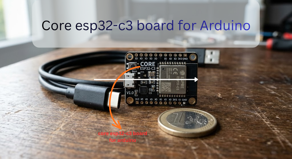
“Core board” isn’t a brand name. It’s more of a description. It means the board is stripped down to the essentials: the chip, a voltage regulator, a USB-to-serial connection, and not much else. No screen. No battery holder. No extras. Just enough to power it up and start writing code.
That’s the whole point. These boards are meant to be a building block, not a finished gadget. A lot of them even have small stamp-hole pads along the edge, so someone could solder the whole thing directly onto a bigger custom board later.
Under the hood, every Core ESP32-C3 board runs the same chip: Espressif’s ESP32-C3, an affordable microcontroller with 2.4GHz WiFi (802.11 b/g/n), Bluetooth 5.0 LE, and 400KB of RAM. It’s become a go-to for anyone building simple connected gadgets on a budget.
Core ESP32-C3 vs a Regular ESP32 (The Honest Version)
A lot of buying guides skate past the real differences here. I won’t.
The classic ESP32 has two processor cores. The ESP32-C3 has one. That single core also uses a different architecture called RISC-V, instead of the Xtensa cores found in the older ESP32 and ESP8266 chips. In everyday Arduino projects like blinking LEDs, reading sensors, or hosting a small web page, you won’t notice a speed difference. Where it matters is heavy multitasking, running two things at once that genuinely need separate cores. The C3 can’t do that the way the classic ESP32 can.
The C3 also has fewer usable GPIO pins than a full-size ESP32 board. It drops Bluetooth Classic entirely in favor of Bluetooth Low Energy only. On the plus side, it draws less power, costs less, and packs noticeably more RAM than the ESP8266 it was built to replace. If you’re still deciding between chips, our breaks the older chip down in more detail.
| Feature | ESP32-C3 | Classic ESP32 |
|---|---|---|
| CPU | Single-core RISC-V, 160MHz | Dual-core Xtensa, up to 240MHz |
| RAM | 400KB SRAM | Varies by module, generally more |
| Bluetooth | BLE only | BLE and Classic |
| GPIO pins | Fewer, around 15 usable | More |
| Typical price | Lower | Higher |
One catch to flag: because the C3 runs on RISC-V, a handful of older libraries written with Xtensa-specific shortcuts won’t compile for it. Rare by now, since most popular libraries have caught up, but if you’re pulling in some ancient GitHub repo from 2018, keep it in mind.
If this is your first microcontroller ever, a standard ESP32 dev board gets you more tutorials and a more forgiving GPIO layout. If you already know your way around Arduino and want something smaller and cheaper for a battery project, the Core ESP32-C3 is the better call.
What’s Actually on This Tiny Board
Flip your board over and you’ll usually find:
- A USB port, either micro USB or USB-C depending on the seller. It connects through a chip that translates USB into serial data your computer understands. Some boards use a CH340 chip, others use a CP2102, and a few skip the extra chip entirely and rely on the ESP32-C3’s own built-in USB connection. That detail decides whether you need to install a driver at all.
- Two small buttons: BOOT, which puts the chip into programming mode, and RST, which restarts it.
- An onboard LED. This is the part that trips almost everyone up, because the pin isn’t standardized. Depending on the manufacturer, it might sit on GPIO2, GPIO8, GPIO12, or GPIO13. There’s no way to know for sure until you test it, which we’ll do in a minute.
- A few power pins (3V3, 5V, GND) and rows of GPIO pins along both edges, usually printed in tiny, easy-to-misread text.
![the bottom of the board with USB port, BOOT/RST buttons, and LED labeled]](https://arduinocraft.com/wp-content/uploads/2026/05/Core-esp32-c3-board-for-Arduino-3-1024x559.png)
Setting Up Arduino IDE for the Core ESP32-C3
This is the setup process that’s worked for me across three different clone boards.
Step 1: Install Arduino IDE 2. If you don’t already have it, grab the current version from Arduino’s official site. Older 1.8-style installs still work, but IDE 2 makes the rest of this process easier.
Step 2: Add ESP32 board support. Open the Boards Manager (the icon on the left sidebar, or Tools > Board > Boards Manager), search “esp32,” and install the package called “esp32 by Espressif Systems.” If it doesn’t show up in the search, go to File > Preferences and paste this into the Additional Board Manager URLs field:
Espressif keeps a full official installation walkthrough if you want every step with screenshots, and their GitHub page lists exactly which chips each version supports.
Step 3: Plug in the board and pick your settings. Use an actual USB data cable here, not one of the charge-only cables bundled with cheap power banks. That single mistake cost me an entire afternoon the first time.
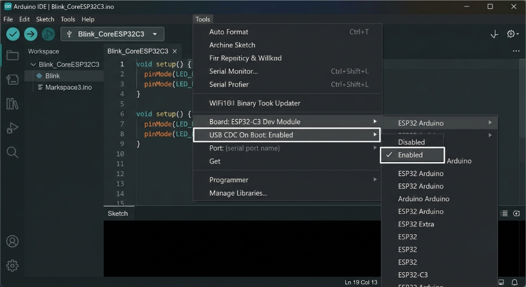
Under Tools > Board, search for “ESP32C3 Dev Module.” This generic option works for the vast majority of Core ESP32-C3 clones, including the ones sold under different brand names. Under Tools > Port, pick whichever COM port (Windows) or /dev/cu.usb… (Mac) shows up when the board is plugged in.
One setting is easy to miss: USB CDC On Boot. Set it to Enabled if you want the Serial Monitor to show output over the USB connection at all. I skipped this once and spent twenty minutes convinced my board was dead, when really the Serial Monitor just wasn’t listening on the right channel.
Uploading Your First Sketch
Time for the classic blink test. Since the LED pin varies by board, I write mine with a variable at the top so it’s easy to change:
cpp
#define LED_PIN 8  // try 2, 12, or 13 if this pin doesn't blink

void setup() {
  pinMode(LED_PIN, OUTPUT);
}

void loop() {
  digitalWrite(LED_PIN, HIGH);
  delay(500);
  digitalWrite(LED_PIN, LOW);
  delay(500);
}
Upload it. If nothing happens, don’t panic and don’t assume the board is dead. Swap the pin number and try again. On some boards the LED is even wired backward (active low), so if it’s lit constantly and turns off when you expect it to turn on, flip the HIGH and LOW in the code.
The Upload Problems Nobody Warns You About
A few things went wrong for me more than once. Here’s the shortlist.
Board not showing up as a COM port at all. Nine times out of ten, this is either a charge-only cable or a missing driver. Check Device Manager (Windows) for an unknown device, and install the CH340 or CP210x driver depending on which chip your board uses. Our covers this step by step for Windows and Mac.
Upload hangs on a row of dots and then fails. This means the board didn’t automatically drop into programming mode. Hold down BOOT, tap RST once while still holding BOOT, then release BOOT and try uploading again. It feels clunky, but it works reliably on almost every clone board I’ve tried.
Random resets or the board acting glitchy right after upload. This is usually a power problem, not a code problem. Try a different USB port, a different cable, or a powered hub instead of a laptop’s USB port directly.
Upload succeeds but the code seems to do nothing, or behaves oddly with certain libraries. Check the Flash Mode setting in the Tools menu. Most small Core ESP32-C3 clones need DIO mode rather than QIO, and picking the wrong one can cause hard-to-diagnose failures.
Pins You Should Just Leave Alone
The ESP32-C3 has three GPIO pins, GPIO2, GPIO8, and GPIO9, that control how the chip boots up. Espressif calls these strapping pins. Connect an LED, a pull-down resistor, or a sensor to one of them without knowing what you’re doing, and you can accidentally force the board into the wrong boot mode. Then it just refuses to start.
GPIO9 usually already does double duty as the BOOT button, so treat it as reserved. GPIO12 through GPIO17 are typically wired internally to the board’s flash memory chip, so even though Arduino IDE will let you try to use them, don’t. Save yourself the headache and pick a different pin for your project.
What You Can Build With This Thing
This little board punches above its size for anything that needs WiFi or Bluetooth on a budget. A few ideas that fit it well:
- A WiFi-controlled relay to switch a lamp, fan, or space heater on and off from your phone
- A soil moisture sensor that pings your phone when a houseplant needs water
- A small BLE beacon or asset tag for tracking something around the house
- A compact sensor node reporting temperature or humidity into Home Assistant or an MQTT broker
- A mailbox or door sensor that fires off a notification the moment it opens
If you’re just getting started with this kind of project, ourbeginner-friendly IoT projects with ESP32 boards has a few more ideas to get you moving faster.
Is the Core ESP32-C3 Worth Buying?
For most hobby projects, yes. It’s cheap, usually somewhere around three to five dollars, small enough to hide almost anywhere, and sips very little power, which matters a lot if you’re running it off a battery.
The downsides are real, too. You get fewer GPIO pins than a full-size ESP32 board. Tutorials written specifically for this chip’s RISC-V quirks are less common than the mountain of content for the classic ESP32. And the LED pin lottery between different manufacturers is a minor but constant annoyance.
If you’re buying one, look for a listing that clearly states the flash size (4MB is standard), mentions which USB chip it uses, and ideally includes a labeled pinout diagram in the photos. A lot of the cheapest listings skip this, and that’s exactly how you end up guessing at pin numbers like I did.
FAQs
Is the Core ESP32-C3 the same as the ESP32-C3 Super Mini?
Not the same product, but close enough in practice that a guide written for one will usually carry you most of the way with the other. Both run the same ESP32-C3 chip and use the same Arduino board settings.
Does it work with regular Arduino code and libraries?
Yes, for the most part. The Arduino ESP32 core supports the C3’s RISC-V architecture, and most popular libraries have been updated to work with it. Only a small number of very old, Xtensa-specific libraries may fail to compile.
Which pin is the built-in LED on?
It depends on the manufacturer. Common options are GPIO2, GPIO8, GPIO12, or GPIO13. The quickest way to find yours is to try each one in the blink sketch above.
Why isn’t my board showing up as a COM port?
Check your USB cable first (charge-only cables won’t work), then confirm you’ve installed the correct driver, either CH340 or CP210x, based on the chip on your specific board.
Can this board run on battery power?
Yes. It’s designed with low power use in mind and works well for battery-powered sensors, especially if you put it into deep sleep between readings.
Do I need to install a driver separately?
Sometimes. If your board uses a CH340 or CP210x chip, you’ll need that driver installed. If it connects through the chip’s native USB port instead, your computer may recognize it without any extra install.
Final Thoughts
The Core ESP32-C3 is one of those parts that feels intimidating for about an hour, then turns completely routine. Once you’ve gone through the setup once, gotten the LED to blink, and figured out which pins to avoid, you’ll be reaching for this board constantly for small connected projects.
Ready to build your first project? Grab a breadboard, a sensor you already have lying around, and start with the blink sketch above. Once that LED flashes, you’re past the hardest part.
Disclaimer: Specs, pin assignments, and included components can vary between manufacturers even when boards look identical. Always check your specific board’s markings or documentation before wiring anything, and take normal precautions when working with electronics and USB power.


Leave a Reply