
Using an earphone part with Arduino is one of the cheapest ways to build a sound sensor, since you’re reusing a microphone that’s already sitting in your junk drawer instead of ordering a module. It works, but it’s finicky, and nobody tells you that part upfront.
I found that out the hard way. My first attempt just wired the earphone’s mic wire straight into an analog pin, expecting a clean signal. I got noise, a flat line, and about twenty minutes of confused Googling before I figured out what an electret mic actually needs to function.
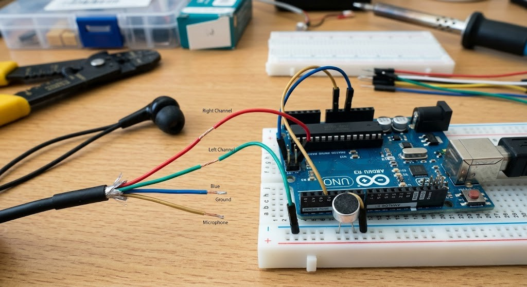
What You’ll Need
- An old wired earphone or headset with an inline mic (not just left/right audio — you need the mic wire)
- Arduino Uno or similar
- A 2.2kΩ resistor (mic bias)
- A 1µF electrolytic or ceramic capacitor (signal coupling)
- Two 10kΩ resistors (voltage divider, to center the signal)
- A breadboard and jumper wires
- Wire strippers or a small blade
You don’t need anything exotic here. This is a spare-parts-bin project, which is really the whole appeal.
Why an Earphone Can Work as a Sensor
Most earbuds with a built-in mic (the kind that came with a phone) use a tiny electret condenser microphone. It’s the same basic component used in dedicated Arduino sound sensor modules like the KY-038 or LM393.
The difference is that those modules already include the support circuit: bias resistor, amplifier, sometimes a comparator for digital output. A bare earphone mic gives you none of that. You have to build the support circuit yourself, which is really the entire trick of this project.
Key Takeaway: An earphone mic is not “plug and play” like a sound sensor module. It needs a bias voltage and a coupling capacitor before Arduino can read anything useful from it — skip either one and you’ll get silence or noise, not sound.
Wiring It Up
Strip the earphone cable near the plug and identify the mic wire (usually a different color from the left/right audio wires, with a shared ground). A multimeter in continuity mode helps if the colors aren’t labeled.
- Connect the mic wire to one leg of the 2.2kΩ resistor. Connect the other leg to Arduino’s 5V pin. This is the bias voltage — electret mics need a small constant current to work at all.
- From that same junction, run a 1µF capacitor into a voltage divider made from two 10kΩ resistors between 5V and GND. This centers the audio signal around 2.5V, since Arduino can’t read the negative half of an AC signal.
- Connect the midpoint of the divider to A0.
- Connect the earphone’s ground wire to Arduino GND.
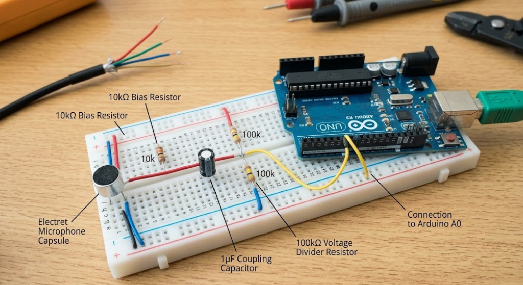
This isn’t the only way to do it, but it’s the simplest version that reliably works on a breadboard without a dedicated preamp chip.
The Arduino Code
The code itself is simple. You’re reading A0 continuously, tracking how far the signal swings from its resting baseline, and flagging it when a sound crosses a threshold.
arduino
const int micPin = A0;
const int ledPin = 13;
int baseline = 512;      // roughly the midpoint from your voltage divider
int threshold = 40;      // adjust this after testing your own setup

void setup() {
  pinMode(ledPin, OUTPUT);
  Serial.begin(9600);
}

void loop() {
  int reading = analogRead(micPin);
  int deviation = abs(reading - baseline);

  if (deviation > threshold) {
    digitalWrite(ledPin, HIGH);
    Serial.println("Sound detected");
  } else {
    digitalWrite(ledPin, LOW);
  }

  Serial.println(reading);
  delay(5);
}
Open the Serial Plotter (Tools → Serial Plotter) before you touch the threshold value. Watching the raw waveform is the only way to know what “quiet” actually looks like on your specific earphone.
Calibrating Your Threshold
Every earphone mic behaves a little differently, so don’t copy someone else’s threshold number and expect it to work. Watch your baseline reading in a silent room first, then clap or talk near the mic and note how far the number swings.
Set your threshold somewhere between those two numbers, closer to the quiet-room reading if you want sensitivity, closer to the loud swing if you want to ignore background noise. This calibration step is the single biggest reason beginner builds fail people skip it and assume the code is broken when it’s really just tuned wrong.
Mistakes That Wreck the Signal
- Forgetting the bias resistor. Without it, the electret mic has no operating current and gives you a flat, dead reading.
- Skipping the coupling capacitor. Wiring the mic directly to A0 clips half the waveform and gives you garbage data.
- Using an earphone with no mic wire. Cheap wired earbuds sometimes only carry left/right audio with no microphone conductor at all. Check before you cut the cable.
- Expecting speech recognition. This circuit detects volume changes, not words. It’s a clap detector, not a voice assistant.
- Long, unshielded wires. Earphone cables pick up 60Hz hum from nearby power sources. Keep the run from mic to breadboard short.
When to Just Buy a Sound Sensor Module Instead
Here’s the honest trade-off. A KY-038 or LM393 sound sensor module costs a few dollars and already has the bias resistor, amplifier, and sensitivity potentiometer built in. If you want a reliable clap switch or noise-triggered project without troubleshooting a breadboard circuit, buying the module is genuinely the better call, and reliable step-by-step wiring for that route is well covered elsewhere (LastMinuteEngineers has a solid walkthrough on connecting a sound sensor module to Arduino).
The earphone route makes sense when you’re working from spare parts, learning how electret mics actually behave, or just enjoy the “I built this from junk” satisfaction. It is not the more reliable option, and it’s fair to know that going in.
FAQs
Does using an earphone mic damage the Arduino? No. The signal from an earphone mic is a few millivolts, well within what an analog pin can safely read once it’s biased and coupled correctly through the resistor and capacitor described above.
Can this detect specific words or voice commands? No. It only measures volume changes. Recognizing speech needs a microcontroller with more processing power or an external module built for voice recognition.
Why is my reading stuck at one number? That almost always means the bias resistor is missing or the mic wire was misidentified. Recheck continuity with a multimeter before assuming the code is at fault.
Can I use earbuds without an inline mic? No. You need a headset or earbuds that specifically include a microphone wire, usually the kind bundled with phones for calls.
Conclusion
An old earphone can absolutely work as a functional Arduino sound sensor once you understand what an electret mic actually needs: a bias voltage and a coupling capacitor. It won’t match the reliability of a dedicated sensor module, but for a spare-parts build, it’s a genuinely satisfying weekend project that teaches you more about how microphones work than a plug-and-play module ever will.
Try it, watch the Serial Plotter while you calibrate, and don’t skip the bias resistor.
Disclaimer: This project involves cutting cables and working with basic electronic components. Always disconnect power before wiring changes, and supervise children if they’re helping with the build.





Leave a Reply