Author Note: I have built three 3D printer controllers and a handful of robotics rigs on the Mega 2560, and most of my early mistakes came from misreading the pinout. This guide is written from that hands-on experience, not from a datasheet copy-paste.
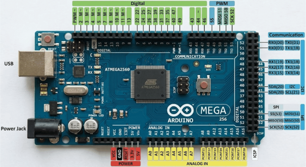
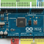
Arduino Mega 2560 pinout covers 54 digital pins, 16 analog inputs, four hardware UARTs, dedicated SPI and I2C lines, and 15 PWM outputs. If you only remember one thing, remember this: pins 0 and 1 are reserved for USB serial, pins 20 and 21 double as I2C, and pins 50 to 53 handle SPI.
Why the Mega 2560 Has So Many Pins
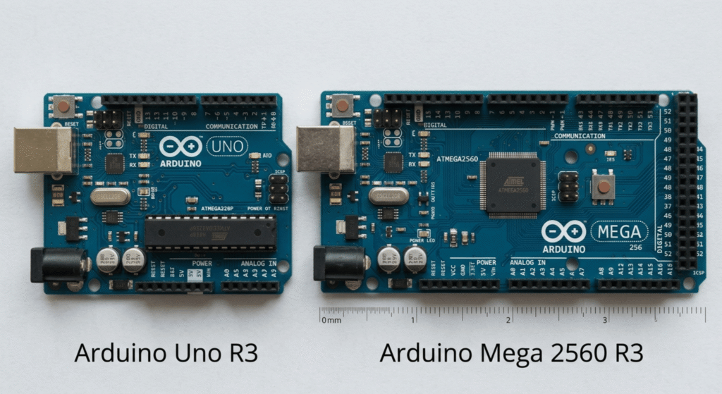
I bought my first Mega 2560 for a CNC build that had outgrown my Uno. The Uno ran out of pins halfway through wiring the stepper drivers, limit switches, and an LCD screen. That is the whole reason the Mega exists. It is built around the ATmega2560 chip, and it gives you room to run big projects without daisy chaining shift registers or cutting features.
The board packs 54 digital pins, 16 analog inputs, four serial ports, and a dedicated SPI bus, all on one 101.5mm by 53.3mm footprint. That is roughly three Unos worth of I/O on a single board.
Digital I/O Pins
Pins 0 through 53 work as general digital input or output using pinMode(), digitalWrite(), and digitalRead(). Every one of them runs at 5 volts and can safely source or sink 20mA, with 40mA as the absolute ceiling before you risk damage.
Pin 13 has a small built in LED wired directly to it, which is handy for a quick blink test the moment you plug in a new board.
Key Takeaway: Treat pins 0 and 1 as off limits for general wiring if you plan to use the USB serial monitor. Anything you send to those pins can collide with data going to your computer.
PWM Pins
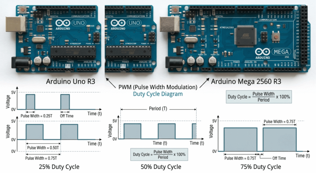
Fifteen pins support pulse width modulation through analogWrite(): pins 2 through 13, plus 44, 45, and 46. These pins fake an analog signal by switching on and off fast enough that an LED, motor, or speaker reads it as a smooth voltage change.
Most PWM pins run near 490 Hz. Pins 4 and 13 run closer to 976 Hz because they share a timer with core board functions. That difference rarely matters for dimming an LED, but it can matter if you are driving audio or a sensitive motor controller.
Analog Input Pins
Pins A0 through A15 read analog voltages between 0V and 5V and convert them into a number between 0 and 1023, giving you 10-bit resolution. This is where your potentiometers, thermistors, and analog sensors connect.
A common rookie move is wiring an analog sensor straight into a digital-only pin and wondering why the readings look flat. Analog sensors need an A-labeled pin, not a numbered digital one.
UART and Serial Pins
This is the feature that sold me on the Mega. It has four independent hardware UARTs, so you can talk to a GPS module, a Bluetooth chip, and a debug console at the same time without any of them stepping on each other.
- Serial0: pin 0 (RX0), pin 1 (TX0), shared with USB
- Serial1: pin 19 (RX1), pin 18 (TX1)
- Serial2: pin 17 (RX2), pin 16 (TX2)
- Serial3: pin 15 (RX3), pin 14 (TX3)
Keep Serial0 free while you are uploading code or watching the serial monitor. Use Serial1 through Serial3 for external modules so your USB debugging never gets interrupted.
SPI Pins
SPI lives on pins 50 through 53:
- Pin 50: MISO
- Pin 51: MOSI
- Pin 52: SCK
- Pin 53: SS
This trips people up who are used to the Uno, where SPI sits on pins 10 through 13. If you grab an old Uno shield that wires SPI directly to those pins instead of through the ICSP header, it will not talk to your Mega correctly. Shields that use the ICSP header work fine because that header carries the same signals on both boards.
I2C (TWI) Pins
I2C runs on pin 20 (SDA) and pin 21 (SCL). Both pins have built in pull-up resistors that cannot be switched off in software, so keep that in mind if your sensor module also ships with its own pull-ups. Stacking two sets of pull-ups on the same line usually still works, but it is worth knowing if you run into flaky readings.
Interrupt Pins
The Mega gives you six external interrupt pins: 2, 3, 18, 19, 20, and 21. Compare that to the Uno’s two, and you can see why the Mega is the better pick for anything involving rotary encoders, emergency stop buttons, or fast pulse counting.
One catch: pins 20 and 21 are already doing I2C duty. Using them as interrupts at the same time as I2C communication is possible but adds complexity, so most of my builds reserve 2, 3, 18, and 19 for interrupts and leave 20/21 dedicated to I2C.
cpp
// Example: external interrupt on pin 2 for a rotary encoder or button
const byte interruptPin = 2;
volatile bool triggered = false;

void setup() {
  Serial.begin(9600);
  pinMode(interruptPin, INPUT_PULLUP);
  attachInterrupt(digitalPinToInterrupt(interruptPin), onPulse, FALLING);
}

void loop() {
  if (triggered) {
    Serial.println("Pulse detected");
    triggered = false;
  }
}

void onPulse() {
  triggered = true;
}
Power Pins
- 5V: regulated output for sensors and logic
- 3.3V: for 3.3V-only modules, limited current draw
- VIN: raw input voltage when powering from an external supply
- GND: multiple ground pins scattered around the board
- AREF: sets a custom reference voltage for analog reads when needed
Do not feed 12V straight into the 5V pin. That mistake fries boards faster than almost anything else, and I have seen it happen on a shared workbench more than once.
Pin Conflicts to Watch For
| Pins | Primary Use | Also Used For | Conflict Risk |
|---|---|---|---|
| 0, 1 | Digital I/O | USB Serial (Serial0) | High during upload |
| 14, 15 | Digital I/O | Serial3 | Medium |
| 16, 17 | Digital I/O | Serial2 | Medium |
| 18, 19 | Digital I/O | Serial1, Interrupts | Medium |
| 20, 21 | Digital I/O | I2C, Interrupts | Medium |
| 50-53 | Digital I/O | SPI | High with shields |
A Real Wiring Example With Code
On a recent build I used a GPS module on Serial1 while logging debug messages over the USB serial monitor. This is exactly the kind of job the Mega was built for.
cpp
// GPS module on Serial1 (pins 18/19), debug output on Serial0 (USB)
void setup() {
  Serial.begin(9600);   // USB debug console
  Serial1.begin(9600);  // GPS module
}

void loop() {
  if (Serial1.available()) {
    String gpsData = Serial1.readStringUntil('\n');
    Serial.print("GPS: ");
    Serial.println(gpsData);
  }
}
Wire the GPS module’s TX pin to the Mega’s pin 19 (RX1) and its RX pin to pin 18 (TX1). Power it from 5V and GND. Open the serial monitor and you will see live GPS sentences printing out while the GPS wiring never touches your USB debug line.
Common Beginner Mistakes
- Wiring an analog sensor to a numbered digital pin instead of an A-pin
- Using pins 0/1 for a sensor, then wondering why uploads fail
- Assuming SPI is on pins 10-13 like the Uno
- Forgetting that 20/21 already carry I2C pull-ups
- Powering a 3.3V module from the 5V rail
FAQs
How many pins does the Arduino Mega 2560 have? The Arduino Mega 2560 Pinout has 54 digital I/O pins and 16 analog input pins, for 70 usable I/O pins total, plus dedicated power and ground pins.
What is the difference between the Mega 2560 and Uno pinout? The Mega has far more I/O, four hardware UARTs instead of one, six interrupt pins instead of two, and SPI on pins 50-53 instead of 10-13.
Which pins are PWM on the Arduino Mega 2560? PWM output is available on pins 2 through 13, plus pins 44, 45, and 46, giving 15 PWM-capable pins in total.
Can I use all six interrupt pins at once? Yes, pins 2, 3, 18, 19, 20, and 21 can all be active interrupts at the same time, though 20 and 21 also carry I2C traffic.
What voltage do the digital pins run at? All digital pins operate at 5V logic and can safely handle up to 20mA continuous current per pin, 40mA as an absolute maximum.
Conclusion
The Arduino Mega 2560 pinout looks intimidating the first time you count 70 pins staring back at you, but it breaks down into a handful of simple groups once you know what each one does. Learn the UART pins, respect the SPI and I2C reservations, and keep pin 0/1 free during uploads, and the rest of your wiring gets a lot easier.
CTA: Save this pinout guide before your next build, or if you are still picking parts.



Leave a Reply